Mechanical design
Detailed Description of the Design Draft Up to June 2012
Frame
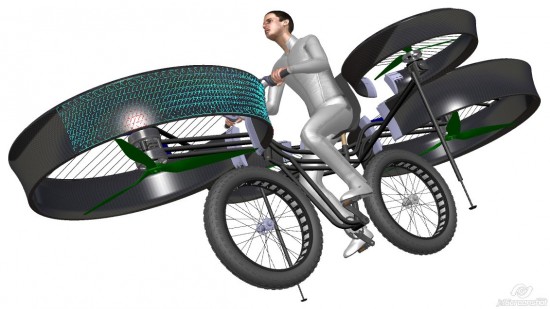
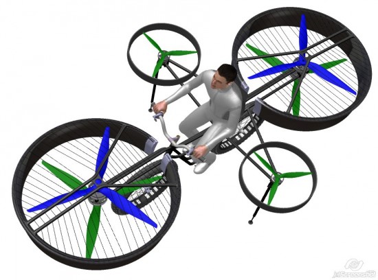
The frame has gone through several phases of conceptual design. Finally, the variant we have chosen is the one similar to the classic shape of a mountain bike, the top part of which is realised as a truncated truss consisting of three parallel tubes. All the necessary electronic should be fitted in the inner space of the truss, including the power distribution for the motors` feed. Besides, this space will be easy to cover.
As for the connection of the propellant units, we have chosen the variant which allows removing the propellant unit set (a console with motors and propellers) to facilitate its transportation. The console is only pushed on the adaptor in the frame and fixed by screws.
An open-ended question is the space among the seat tube, the main girder and the front pair of tubes where there will be the container with a set of LiPol batteries. The space will need to be extended and the container`s position optimized to achieve the right position of the machine`s centre of gravity.
Propeller’s Safety Casing (Baskets)
Both safety baskets (the big one and the small one) will be realised as one compact composite part with an inserted aluminium brace to reinforce and eliminate vibration in the longitudinal axis. At the point of the frame`s passage the large basket will be divided, the ends will be equipped with aluminium shims or an additional brace. The casings will also be reinforced with a welded construction in the shape of Y according to the original design, between the construction and the casing there will be nylon stringing, which will increase the stiffness of the basket even more.
Springing
We abandoned the initial idea to use the gas-liquid dampers (a telescopic descent fork at the front and a swing fork at the back) to soften the landing impact, due to the higher weight of the components which would have an inconvenient influence on the weight of the whole bike.
We discovered a convenient alternative for springing, i.e. special “winter wheels” with wide and high tyre profile. The weight of the wheels will be lower than in case of the telescopic descent fork or rear swing fork. The damping capacity of such wheels may not fully eliminate potential vibrations of the propeller units when landing, but due to time reasons and construction reasons we consider such a solution to be sufficient. Regarding the weight, the solution is fully satisfactory.
Container with Accumulators
For a long time, placing the container with accumulators has been a red-hot topic. As the total weight of the LiPol cells exceeds 20kg, they will significantly influence the position of the machine`s centre of gravity. The first design draft supposed the container will be placed in the space between the seat and the rear propellant unit. However, it was inconsistent with the balance of the machine and, what is more the centre of gravity was placed too high. Another variant supposed half of the cells at the front safety casing, which improved the balance but meant that replacing the cells would be complicated. Also, it would be necessary to lengthen the power conductors for balancing the currents to take the power off the cells.
For now, the final position of the accumulators follows the last draft. The accumulator cells will be placed one above another in ten blocs, each with 14 cells connected in series. The container with cells will be design to be fully removable out of the frame to secure easy replacement. The cable outlets will be connected to one power conductor which will be connected to a connector placed at the container (the bike`s main power distribution will be connected to it).
Seat
The seat will be a composite anatomically shaped shell which will support the pilot up to his loins. The lower part of the seat will have an integrated connecting part allowing attachment to the standard seat-tube so that the seat can be adjusted lengthwise and rotated round the horizontal transversal axis. A safety belt will be attached to the seat allowing quick fastening.
Stabilisation bearing
Stabilisation bearing will be realised according to the last sketch. Springing will be secured by a purchased gas strut which will be integrated in the main bearing tube. We have not solved the subassembly at the point of the contact between the bearing and surface which would secure slipping on the surface in case of horizontal move during takeoff or landing so that the bearing is not deformed or destroyed. One possibility is to create a mechanical lock which would, in case of an uncontrolled touch-down, secure that the bearing will “break off” so that the frame is not deformed.
Control unit
The control unit and control elements are technically the most complicated parts of the machine. The final solution has not been chosen so far. On principle, there are the following options:
1. A ready module by The HowerFly Company
This is a “box solution” which integrates the control unit and the sensors. The producer has been contacted and possible amendments necessary for the bike`s rotors configuration are being discussed. At the moment, our decision depends on the producer`s opinion. In case we would like to purchase just one piece they may not be willing to make the necessary changes.
As for the ready module the stabilization in the air and the functionality of the whole system would be very good.
2. A tailor-made solution
In case we choose this option it would be necessary to assemble the control unit of partial components (MCU, sensors etc.) and program it. This would be a tailor-made solution. It would be a more time-consuming solution and the stability might not be sufficient and comparable to the first option. On the other hand, there would be more possibilities of the configuration. The whole solution would be assembled and brought to life by Mr. Chmelar from University in Pardubice, The Faculty of Electrical Engineering and Informatics.
At present we are considering the first option. If we do not come to an agreement with the producer of the HowerFly solution, we will change over to the second option.

Current Tasks (up to June 2012) Regarding the Design
Technodat
- Finish moulding of the CAD data of the purchased components
- Draft the design of the “dashboard”
- Create a 3D model of the wiring
- Draft design of handlebars adjustment combined with the control element
- Define materials to determine the weight
- Update the main set and check the model
- Carry out rough physical FEM calculation of the frame
Duratec
- Finish the frame construction, its bracing, fixing the main motors and the safety casings
- Adjust the frame for the container with accumulators to be placed
- Finish the construction of the front fork
- Finish the construction of both the large and the small safety baskets
- Design more detailed shape of the seat with safety belts fixed to it
- Draw up the summary of the purchased components` weight to determine the total weight
- Provide models of brake disks and stirrups
Evektor
- Finish the construction of the container for the accumulators
- Design and obtain the connection of the accumulator cells (running of the power conductor, choose a convenient connector) from the supplier
- Discuss the control unit with the HowerFly producer
- Design integration of the gas strut into the bearing, design the slide component (rotating wheel, coulisse etc.) to secure the slide of the bearing in case it touches surface
- Finish the 3D models of the propellers
- Prepare a mock-up to connect all the wiring and seasoning of the whole system (including the wiring diagram)

Digital mock-up (May 2012)
no images were found
